
 EN
How dampers electric actuator realizes automatic air volume regulation in ventilation ducts?
In a ventilation duct, a damper becomes an automatic air-volume device only when its blades, electric actuator, control signal, and feedback strategy work as one loop. The actuator does not measure airflow by itself. It turns a controller command into blade movement; the duct design, sensors, and commissioning determine whether that movement produces the intended air volume. This distinction matters when specifying dampers for industrial ventilation, smoke-control interfaces, or building air-distribution systems.
From a building-services engineering viewpoint, the practical question is not simply “can the blades open and close?” It is whether the selected dampers can hold a useful position against duct pressure, respond predictably to demand, and be verified after installation. A well-matched electric actuator gives the system repeatable motion. A well-commissioned control loop turns that motion into stable airflow regulation.
The basic control chain: signal, torque, blade position, airflow
Automatic regulation starts at the control layer. A building management system, local controller, thermostat, pressure controller, or airflow controller calculates a required damper position. Depending on the project, that request may be a floating open/close signal, a staged signal, or a modulating command such as 0–10 V, 2–10 V, or a network value. The electric actuator receives that command and rotates its output shaft through a defined angle.
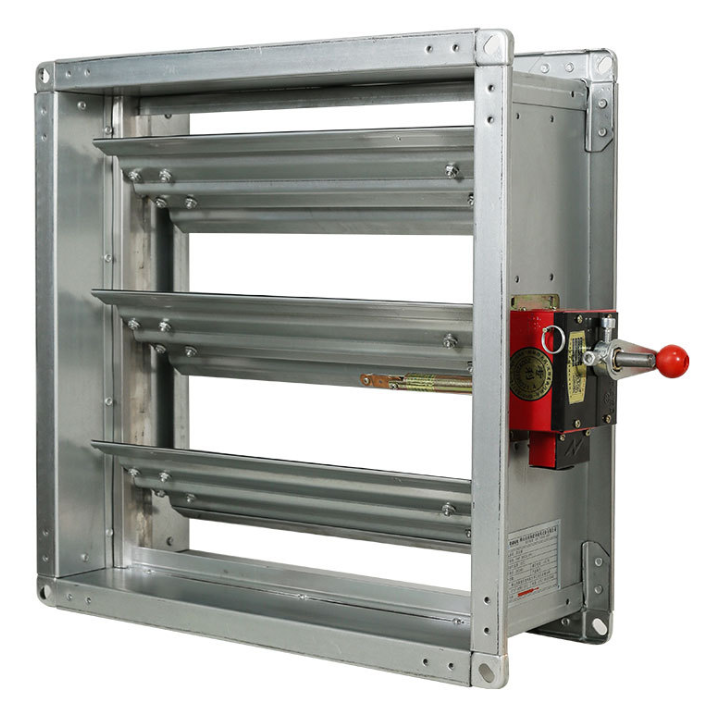
The shaft drives the damper linkage, which rotates one blade or a bank of blades. As the effective opening changes, the resistance through the duct section changes. With the same fan and duct conditions, a smaller free area generally restricts flow and a larger free area permits more flow. That is the physical mechanism behind automatic air-volume regulation by dampers.
However, blade angle is not the same as airflow. The resulting volume depends on upstream static pressure, downstream resistance, fan operation, duct geometry, blade design, leakage, and interactions with other branches. If a branch is starved because the fan cannot maintain pressure, commanding a damper to 100% open will not create the design airflow. In other words, the actuator controls position; the system controls air volume through the relationship between position and actual duct conditions.
What the electric actuator contributes
Repeatable positioning
Manual adjustment is useful during balancing, but it cannot react to changing occupancy, process loads, or pressure conditions. A modulating actuator can move to intermediate positions repeatedly, allowing the controller to trim airflow rather than use only full-open or full-closed states. This is particularly useful where zones need different supply or exhaust rates at different times.
Enough torque for the installed damper
An actuator must overcome blade friction, seals, linkage resistance, and the pressure forces acting on the blades. Torque selection should therefore follow the damper size, blade arrangement, seal type, mounting orientation, and expected differential pressure. Selecting by duct size alone can be misleading. If the available torque is marginal, the indicated position may not represent the blade position the designer intended.
Position feedback and fault visibility
Many actuator configurations provide auxiliary switches, mechanical indication, or electronic position feedback. Feedback lets a controller compare the requested position with the reported position and flag a likely linkage, actuator, wiring, or obstruction problem. It is useful for maintenance, but it still does not prove airflow. For critical volume control, use a suitable airflow, pressure, or terminal-unit measurement strategy as well.
How closed-loop air-volume control works
There are several practical ways to use electric-actuated dampers. The right method depends on how much accuracy and response the application requires.
- Schedule or occupancy control: the controller opens or closes a zone damper when a room is occupied or a process is active. This is automatic, but it is usually position control rather than measured airflow control.
- Temperature-driven control: a room or supply-air temperature loop changes blade position to increase or reduce delivered air. The airflow result is indirect, and performance should be validated under representative load conditions.
- Duct static-pressure control: a pressure sensor informs a controller that modulates one or more dampers to maintain a pressure target. This approach can help manage changing branch demand, provided the fan control strategy is coordinated.
- Airflow-measured control: an airflow sensor or calibrated terminal device supplies an actual-flow value. The controller compares measured flow with the setpoint and adjusts the actuator until the error is reduced. This is the clearest route when a branch must maintain a specified air volume.
In a feedback loop, the controller repeatedly calculates the difference between the setpoint and the measured value. It then commands the actuator toward a new position, waits for the duct system to respond, and evaluates the next measurement. Control tuning matters here. An overly aggressive loop can hunt around the setpoint; a very slow loop can leave a zone under- or over-ventilated for too long.
A practical sequence for ventilation-duct dampers
- Define the regulated quantity. Decide whether the project needs simple isolation, position control, static-pressure control, or verified air-volume control. This decision determines whether airflow sensing is necessary.
- Choose the damper construction. Select blade type, frame, seals, leakage performance, and operating pressure for the duct duty. Do not treat a fire or smoke damper as a general-purpose modulating volume-control device unless its intended operation and project requirements support that use.
- Size the actuator. Confirm required torque at the expected pressure and consider linkage geometry. Confirm power supply, control input, fail-safe requirement, run time, and compatible feedback options.
- Install for serviceability. Leave access to the actuator, linkage, inspection points, and sensors. A well-sized component is hard to maintain if it is buried above a ceiling or behind inaccessible ductwork.
- Commission with measured conditions. Stroke the blades, verify direction of rotation, check end stops and feedback, measure airflow or pressure, and document the relationship between command, blade position, and system response.
- Coordinate with the fan. Variable-air-volume behavior at branches affects duct pressure. Fan speed control, minimum airflow limits, and the damper sequence should be reviewed together.
Common reasons automatic regulation disappoints
A frequent mistake is to assume that a 50% actuator command delivers 50% of design airflow. In real ducts, the relationship is rarely linear. Blade geometry and pressure distribution can make a small movement near one end of the stroke more influential than the same movement elsewhere. Commissioning data or a calibrated control device is more reliable than a presumed linear relationship.
Another issue is poor sensor placement. A pressure or airflow sensor placed where turbulence, elbows, transitions, or nearby branches disturb the reading can drive unstable control. If your duct conditions vary substantially, the normal rule of thumb may not hold; measure representative conditions before finalizing the control sequence.
Finally, mechanical details matter. Loose linkage, incorrect blade orientation, insufficient actuator torque, unsealed leakage paths, or a failed feedback signal can all make dampers appear to be a controls problem when the root cause is mechanical. Start troubleshooting by confirming free blade travel and actual blade position, then verify the signal and measured system response.
Choosing the right control scope
For many projects, a basic electric actuator on dampers is enough for automatic scheduling or zone isolation. For a process exhaust branch, laboratory area, or a zone with a defined ventilation target, consider a measured-flow loop and a commissioning plan from the outset. The component choice should follow the operating objective, not the other way around.
Hongpeng supplies ventilation equipment and damper solutions for industrial and building applications. When discussing a project, provide the duct size, airflow target, pressure conditions, control signal, power supply, fail-safe requirement, and any fire/smoke interface requirements. Those details make it possible to evaluate whether the damper and actuator arrangement is appropriate for the control task.
Control and maintenance checklist for dampers
For automatic service, record the tag number for each dampers assembly, actuator torque and stroke, signal range, fail position, and measured airflow. Inspect dampers for free travel before energizing actuators. Verify that adjacent dampers do not create a pressure conflict. During maintenance, compare command, feedback, and airflow; that check is more informative than observing dampers alone. Where many dampers share a fan, change the sequence in steps and record the pressure response. Clean linkages and confirm that dampers return to the intended safe position after a power-loss test where required. Test dampers at minimum, mid-stroke, and maximum command. Compare dampers at the same command after a maintenance change. Label dampers clearly at the access point. Recheck dampers after fan-speed changes. Trend dampers feedback during normal operation. Keep dampers accessible for inspection. These records distinguish an actuator issue from a sensor, fan, or duct issue.
Conclusion
Electric actuators enable dampers to regulate ventilation airflow automatically by converting a control command into repeatable blade movement. Reliable air-volume regulation comes from the complete system: correctly selected damper and actuator, a control signal that matches the application, useful feedback, and on-site commissioning against measured airflow or pressure. Treating those elements as one design problem helps avoid the gap between commanded position and actual ventilation performance.
 Hot News